Workshop
Arduino, VR and Computer vision
In week 2 through 5, we are getting additional workshop about basic Arduino, VR and Computer vision. Each week has it's own assignment. These workshop cover the practical and technical tools and techniques needed for the upcoming lab weeks. These workshop to get your hand on the technology behind all the discussed topics.
Arduino
Assignment
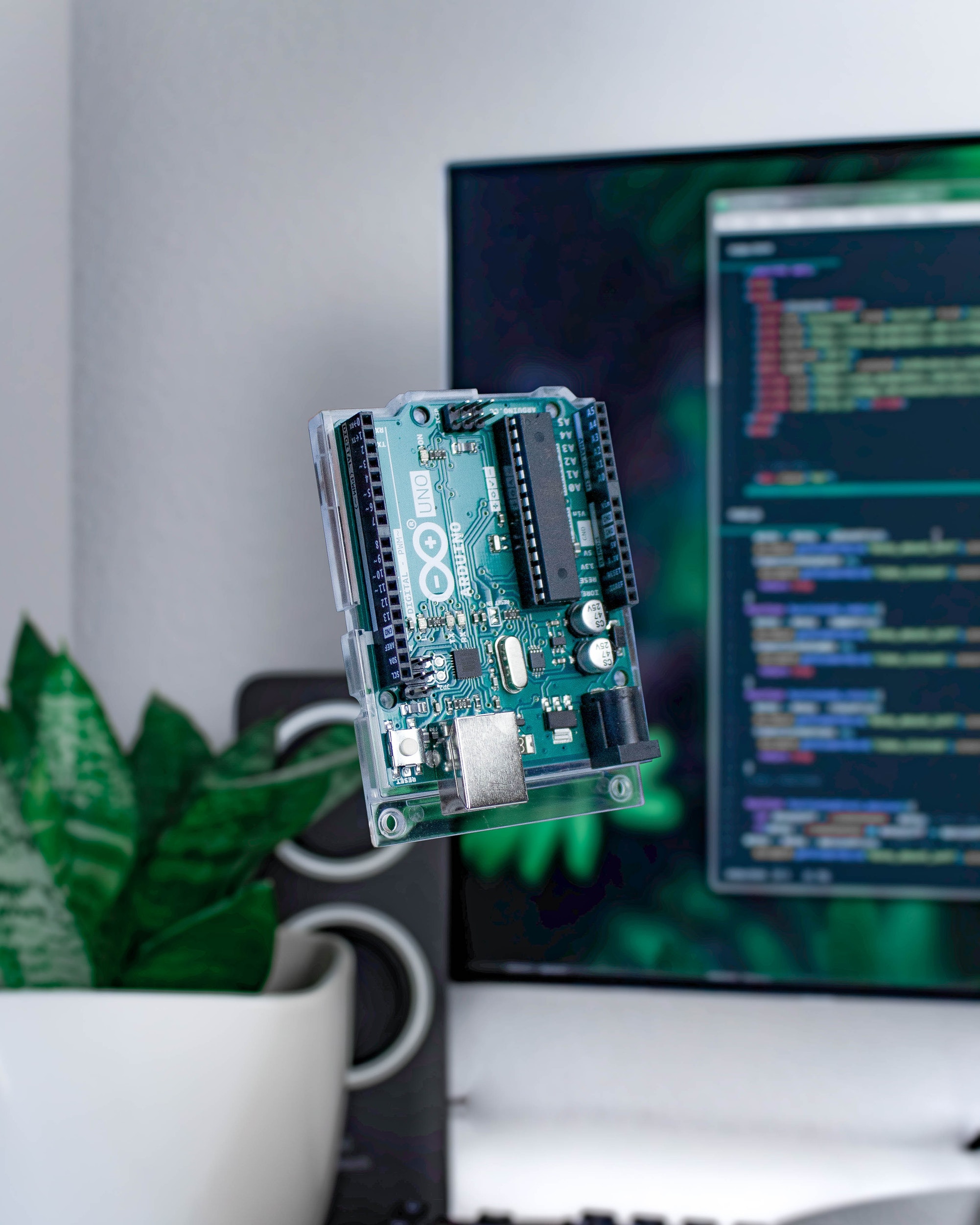
Arduino is small device that is built for developers to learn the basic of combining circuitry and programming. We are running sketches (code) on the Arduino application from our laptops to talk to the Arduino device. There are different input and output devices to play with such as LED, buttons, servomotor, speakers etc. Our assignment is to explain what is happening and show the outcome with the corresponding code. For a nerd like me, I never worked with Arduino before but I am excited to learn. I took a little sneak peak at code and it looks like Javascript so it should be easy to work it.
3C: Blinking LEDS
The exercise here is to let the red LED blink twice faster than the yellow LED.
Below you can find the code that was used to achieve this. Basically we define in setup() the outputs which the 2 LEDS. in the loop() we turn the light on and off and put a delay at half a second delay for one LED and for other LED one second delay.
    void setup() {
        pinMode(LED_BUILTIN, OUTPUT);
        pinMode(12, OUTPUT);
    }

    void loop() {
        digitalWrite(LED_BUILTIN, HIGH);
        digitalWrite(12, HIGH);
        delay(500);
        digitalWrite(12, LOW);
        delay(500);
        digitalWrite(12, HIGH);
        delay(1000);
        digitalWrite(12, LOW);
        digitalWrite(LED_BUILTIN, LOW);
        delay(500);
        digitalWrite(LED_BUILTIN, LOW);
    }
4C: Fading LEDS
The exercise here is to let the red LED blink fade in while the yellow LED fades out.
Below you can find the code that was used to achieve this. Basically we define in setup() the outputs which the 2 LEDS.
In the loop() We used a for loop ironic right? to loop through and increasing the brightness which was defined at 0 which is off and to 255 which is the max brightness for a LED. This creates the fade in effect.
We counter the other LED by subtracting the 255 which is max with the current brightness which is increasing time by time and that will result in decrements thus fading out.
        int redLedPin = 10;
        int yellowLedPin = 9;

        void setup() {
            pinMode(redLedPin, OUTPUT);
            pinMode(yellowLedPin, OUTPUT);
        }

        void loop() {
            for (int brightness=0;
                 brightness < 256;
                 brightness++) {
                analogWrite(redLedPin, brightness);
                analogWrite(yellowLedPin, 255 -brightness);
                delay(10);
            }
        }
6C: Fading LEDS with potentiometer
The exercise here is to control the alternating fade in and fade out LEDs with a potentiometer.
Below you can find the code that was used to achieve this. Basically is the same code from exercise 4c but we have a new input, potentiometer.
When you turn the knob we can read the value from it but the value is different from what we need. That's why we used map() to get the right range of values that we can use for the LEDs.
        int sensorPin = A0; // variable for sensor pin

        void setup() {
            pinMode(sensorPin, INPUT);
            pinMode(10, OUTPUT);
            pinMode(9, OUTPUT);
        }

        void loop() {
            int val = analogRead(sensorPin);
            val = map(val, 0, 1023, 0, 255);
            analogWrite(10, val);
            analogWrite(9, 255 - val);
            delay(200);
        }
7: Controle LED with light
The exercise here is to control the brightness of the LEDs with a light dependent resistor. A light dependent resistor let the amount of voltage through on basis of the amount light on that is on the resistor.
Below you can find the code that was used to achieve this.
We made sure to connect the LDR and use the map() function to get the right range values. We used those value to set the brightness of the LEDs.
As you can see when you cover the LDR, the LEDs will dim.
        int sensorPin = A0; //variable for sensor pin

        void setup() {
            pinMode(sensorPin, INPUT);
            pinMode(10, OUTPUT);
            pinMode(9, OUTPUT);
        }

        void loop() {
            float val = analogRead(sensorPin);
            val = map(val, 0, 1023, 0, 255);
            analogWrite(10, val);
            analogWrite(9, val);
            delay(200);
        }
8: Voltage divider
The exercise here is about to get real, you might want to sit down for this. In this excercise we will explain the voltage divider formula.
The voltage divider formula is: Vo = Vi * R2 / R1 + R2.
Vo stands for voltage output what was the real voltage that is going into a LED, Vi stands for voltage input which is coming from the arduino board which is 5V and R stand for resistance of resistor.
R can be static (220ohm resistor) but also dynamic (a LDR). We are using 2 LDR's in this exercise.
If both LDR’s have the same light source than the voltage output will always be the half since Vo = Vi * R2 / R1 + R2 and R1 = R2 and vice versa. It will be then R/2R which is same as 1/2.
If R2 is in the dark and R1 in light than the Vo is going to be close the Vi. R2 has a higher ohm value and R1 little to none then you’re almost dividing R2 with R2.
Vo = Vi * 5000000 / (5000000 + low value from light).
If R1 is in the dark and R2 in light than the Vo will be small. R2 has a lower value and R1 higher value which you are dividing a small value with a large number resulting a in number almost to zero.
Vo = Vi * low value from light / (5000000 + low value).
In the video you can see the value change when I turn on the lights on.
Its hard to get a very low value since there is still light coming from my window so you wont notice a big difference. But there is a value change;
9B: Processing + Arduino
The exercise here is to link up applications with eachother. Processing is a application that allows you to draw shapes just like on a canvas.
Below you can find the code that was used to achieve this.
We made sure to connect the LDR and use the map() function to get the right range values. We used those value to set the brightness of the LEDs.
As you can see when you cover the LDR, the LEDs will dim.
        //Processing sketch
        import processing.serial.*;
        Serial myPort;
        String sensorReading="";

        void setup() {
            size(400, 400);
            myPort = new Serial(this, Serial.list()[1], 9600);
            myPort.bufferUntil('\n');
        }

        void draw() {
            background(255);
            fill(0);
            text("Sensor Reading: " + sensorReading, 20, 20);
            triangle(30 + float(sensorReading),
                     100,
                     58 + float(sensorReading),
                     45,
                     86 + float(sensorReading),
                     100);
        }

        void serialEvent (Serial myPort) {
            sensorReading = myPort.readStringUntil('\n');
        }
10F: Buttons and LEDs
The exercise here is to play with a new input device which is a button.
When we press 1 button of the two buttons the LED should light up.
Below you can find the code that was used to achieve this.
We first define the inputs which is the two buttons. Every button has a state, when pressed the state changes.
With that in mind we can check if one button is pressed, if so light up the LED.
    int ledPin = 13;
    int buttonPinL = 3;
    int buttonPinR = 2;
    int bPinLState = 1;
    int bPinRState = 1;

    void setup() {
        pinMode(ledPin, OUTPUT);
        pinMode(buttonPinL, INPUT);
        pinMode(buttonPinR, INPUT);
    }

    void loop() {
        bPinLState = digitalRead(buttonPinL);
        bPinRState = digitalRead(buttonPinR);
        if((bPinLState == HIGH && bPinRState == LOW) ||
           (bPinRState == HIGH && bPinLState == LOW)) {
            digitalWrite(ledPin, HIGH);
        } else {
            digitalWrite(ledPin, LOW);
        }
    }
11B: Servomotor
The exercise here is to experiment with a new output device which is the servomotor. servomotors are motors that turn to a precise position like a steering wheel.
We want them to use in a interesting way.
Below you can find the code that was used to achieve this.
We first define the ouput device which is the servomotor.
It uses a position to pin point the rotation position in the servomotor.
With a loop we are changing that position each time.
When the max rotation is reach we reset it back to the beginning. So is the rythm created.
            #include <Servo.h>
            Servo myServo;
            int servoPin = 9;
            int pos = 0;
            void setup() {
                 myServo.attach(servoPin);
            }

            void loop() {
                for(pos = 0; pos < 160; pos += 30) {
                    myServo.write(pos);
                    delay(1000);
                }
                myServo.write(0);
            }
12B: Servomotor + Button
The exercise here is to use to buttons to control the rotation of the servomotor.
One button to rotate right and one button to rotate left.
Below you can find the code that was used to achieve this.
It's actually very easy to do. When pressing a button we increase or decrease the position of the rotation.
We also have to check rotation to make sure it doesn't go below the minimal position or higher than the max.
        #include <Servo.h>
        Servo myServo;
        int pos = 0;
        int buttonPinL = 3;
        int buttonPinR = 2;

        void setup() {
            myServo.attach(9);
            pinMode(buttonPinL, INPUT);
            pinMode(buttonPinR, INPUT);
        }

        void loop() {
            if(digitalRead(buttonPinL)) {
                pos++;
                if(pos < 160) { myServo.write(pos); }
            }

            if(digitalRead(buttonPinR)) {
                pos--;
                if(pos > 0) { myServo.write(pos); }
            }
        }
13B: Sound
The exercise here is to use a speaker to play a melody.
We can make our own melody for this excerise. I chose to play mario theme song.
Below you can find the code that was used to achieve this. Each melody has it's own frequency. If you know the sequence than you can make your own melody.
I search for the melody of mario theme song and copy it in my code. Unmute the video to hear the melody.
    int speakerPin = 8;

    void setup() {
        pinMode(speakerPin, OUTPUT);
    }

    void loop() {
        tone(speakerPin, 660, 100);
        delay(150);
        tone(speakerPin, 660, 100);
        delay(300);
        tone(speakerPin, 660, 100);
        delay(300);
        tone(speakerPin, 510, 100);
        delay(100);
        tone(speakerPin, 660, 100);
        delay(300);
        tone(speakerPin, 770, 100);
        delay(550);
        tone(speakerPin, 380, 100);
        delay(575);
    }
VR Environments
Assignment
This assignment consists of 2 parts.
The first part is to use a projector to project different sources like picture and videos on an objects like walls, pyramide, mannequin and etc.
We called this SAR (Spatial Augmented Reality).
We used a program called MadMapper to map out the object and project something awesome on it.
This program allow us to play with perspective and create 3d looking projection.
Our assignment to use our imagination and make something great.
The second part is to make an VR environment in Unreal Engine.
Unreal Engine is an engine design to make 3d models and environment especially for games.
Our assignment for this part was to create a banana catching game where you can move around.

SAR Process
Spatial Augmented Reality is a way to project different sources such as pictures and videos on different objects.
We followed the tutorial that was given for the installions. That was basically to download MadMapper and setup the projector.
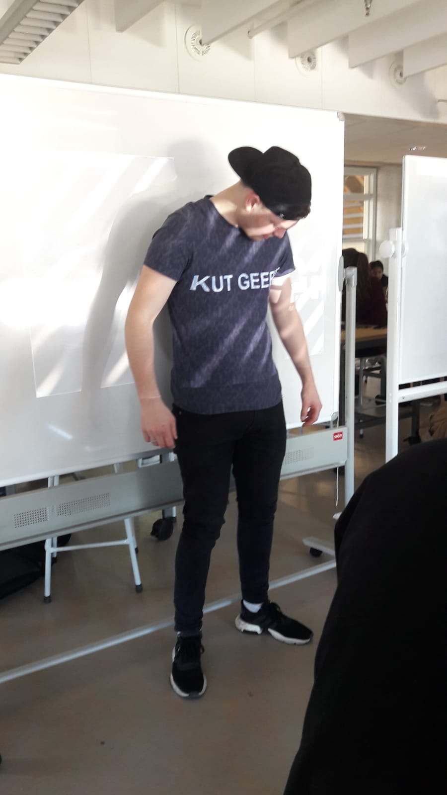
We started to expirement with text on a plain canvas. We kinda created a merchandise for our friend Geert here.
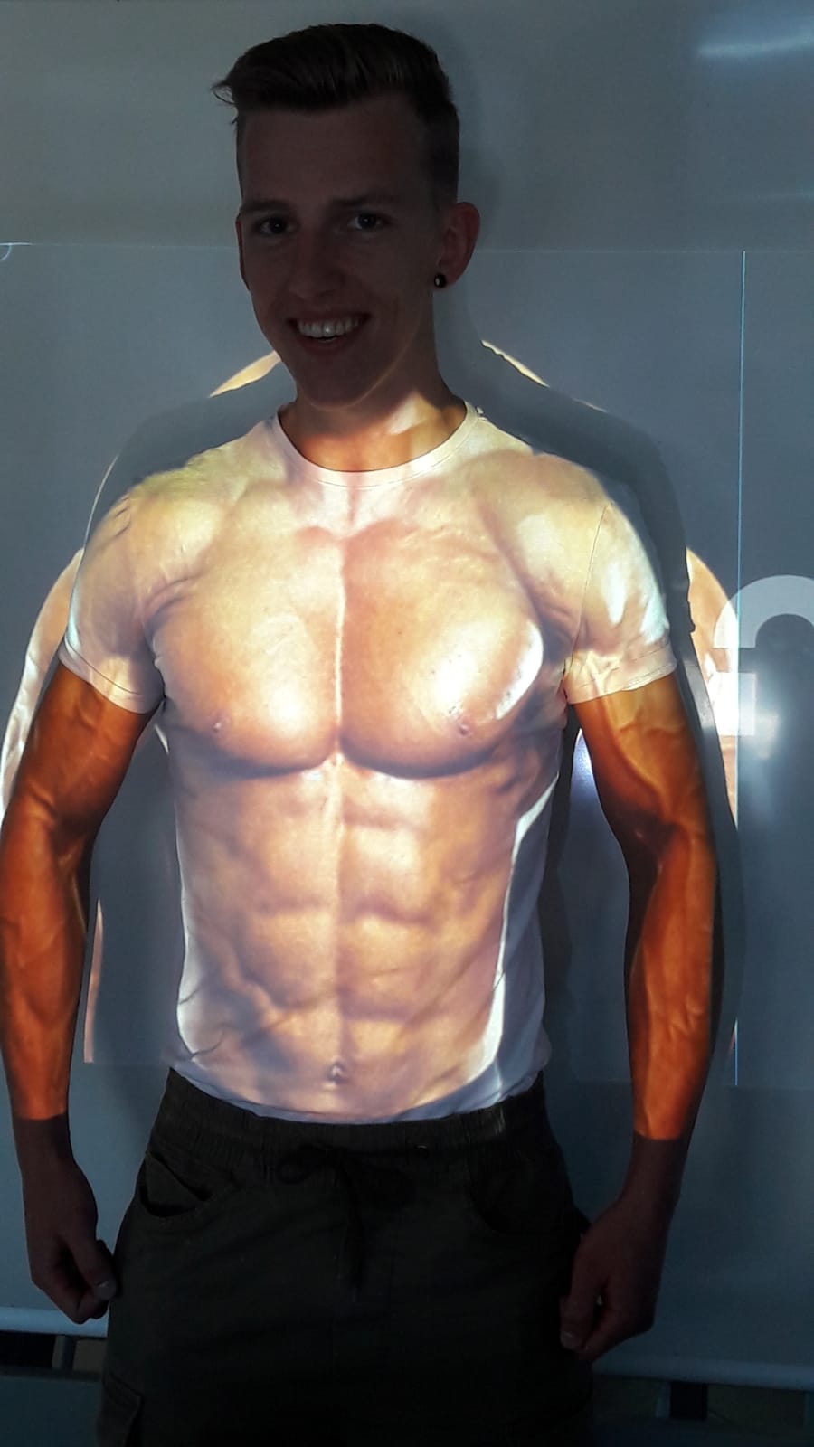
After that we moved into pictures and videos. For the pictures we tried to map a bodybuilder on someone body.
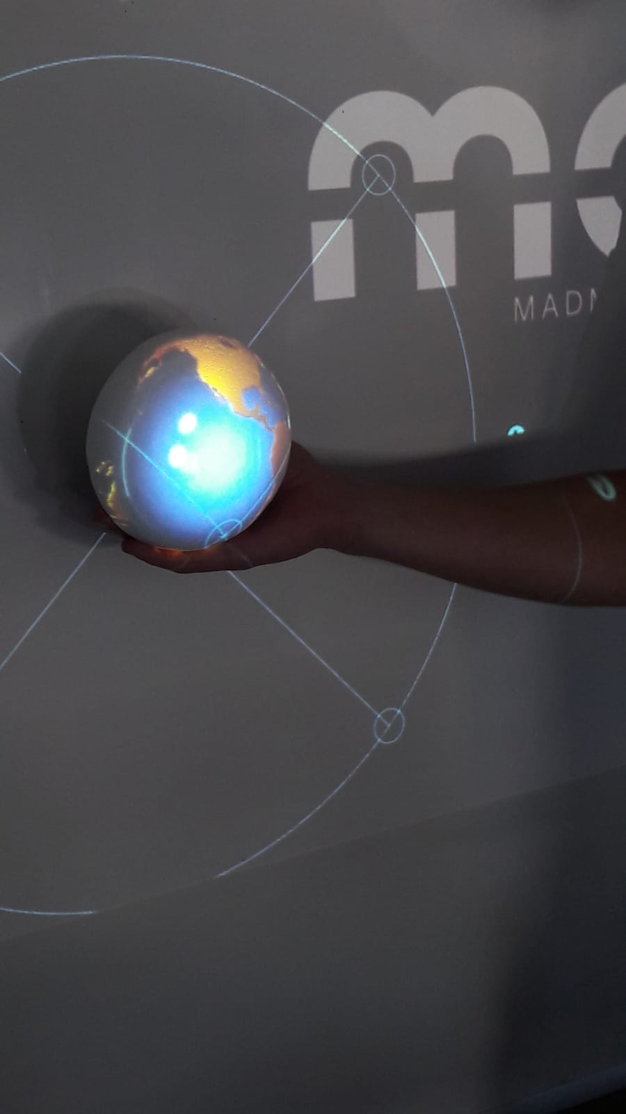
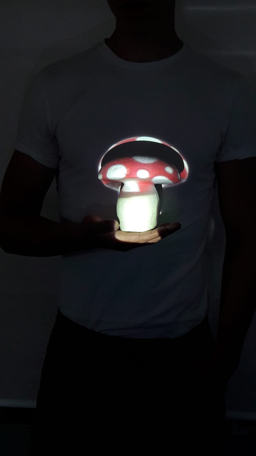
Then we tried to map a world on a someone hand trying to create a 3d object.
We also tried that with a mushroom but it didn't work out was we planned.
I think we need to work on mapping the round edges.
After a lot of experimenting we got hang out it and started to try to out perspective angles. We build a pyramide and taped on a board with the point facing the projector.
We mapped out each side on the pyramide and project different video's.
We also tried to other input like facecam.
We got the facecam working and project the livecam on a mannequin head which was very creepy.
Pictures and video's are on the following page.

Unreal Engine Process
Unreal engine is an engine where you can build environment and games.
Unreal engine is developed by Epic Games.
There is a lot of games made with Unreal Engine. Fortnite a popular game that is build with Unreal Engine.
Our assignment was to follow the given tutorials and which is to interact with a banana.
The assignment consist of 2 parts: First part is to get started with unreal engine by making a banana turntable.
The second part is to make a banana collecting game that goes deeper into events.
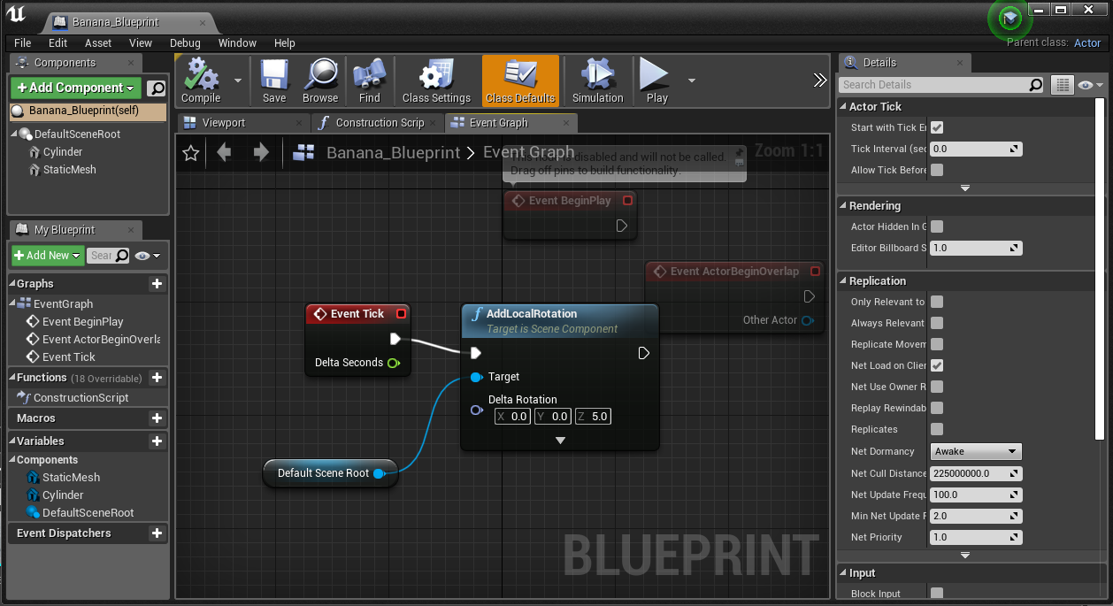
Banana Turntable
The exercise is pretty much to follow a given tutorial on unreal engine to make a turntable with a banana.
On the left you can see the event graph of the banana and the result of the tutorial.
In this graph we define the loop for the frame and we changed the z which makes the banana and the cyclinder spin.
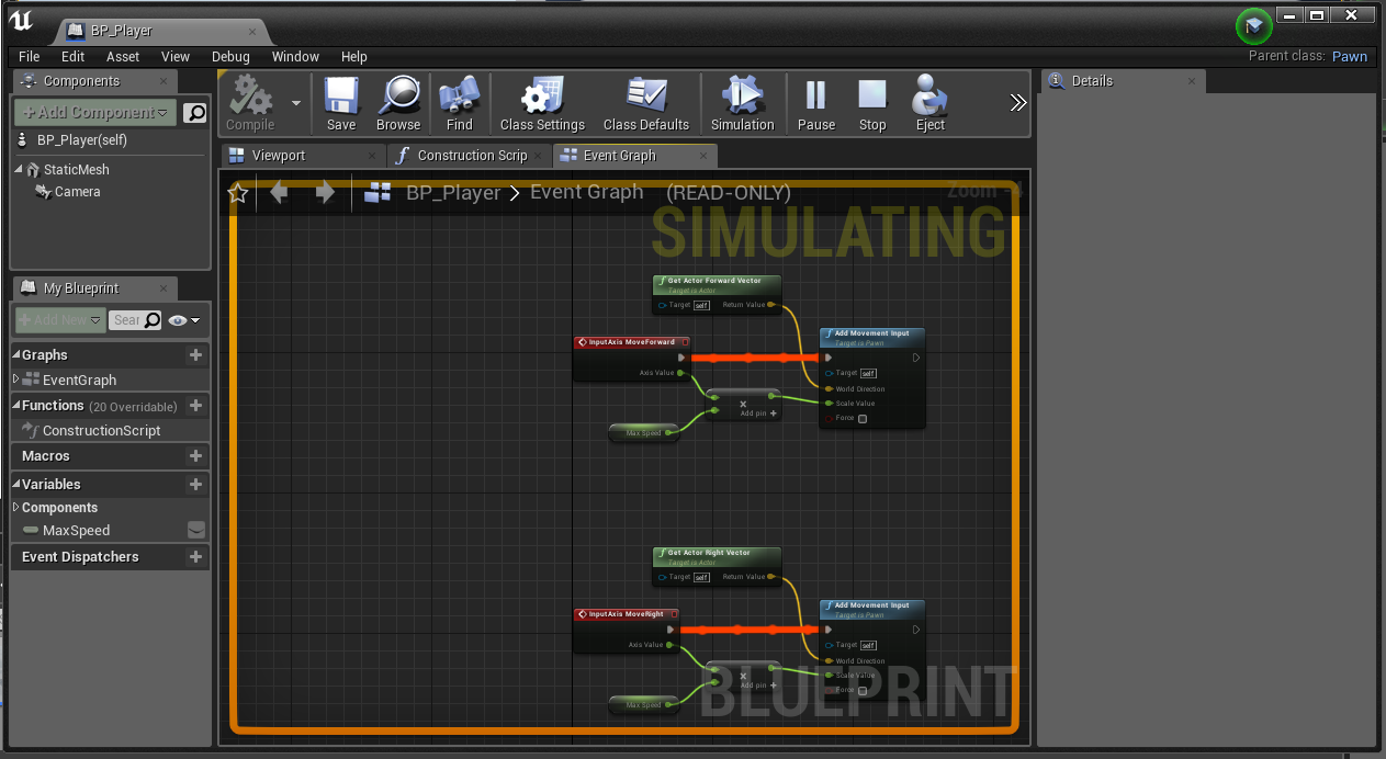
Collecting banana
The exercise is pretty much to follow a given tutorial on unreal engine to make a banana collecting game
On the left you can see the event graph of the player and also the result of the tutorial.
The event graph is where to can attach event to models.
In this graph we defined the movement of the cube, collision and speed.
Computer Vision
Assignment
This assignment is also divided into 2 parts.
In the first assignment we are going to learn how to use Processing.
Processing is an open source programming language and environment for people who want to build interactive systems.
It's also the perfect tool for learning the fundamentals of programming.
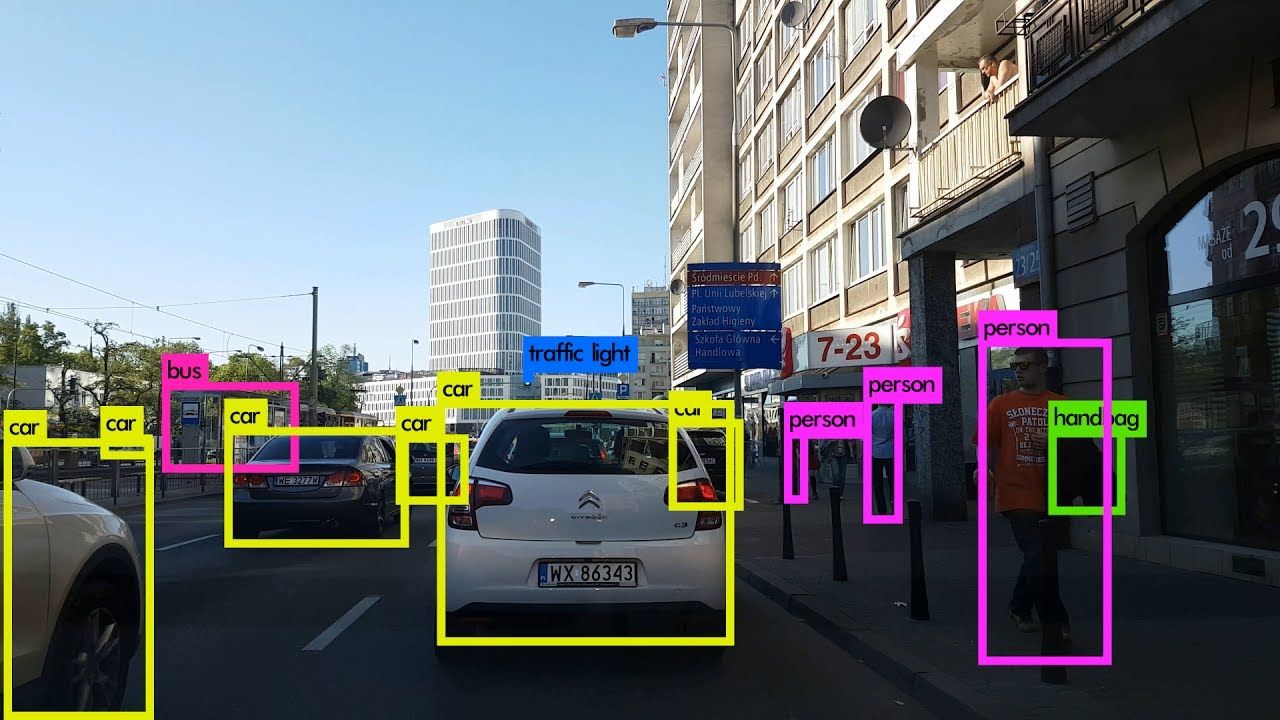
The second assignment is about Computer Vision. Computer vision is a field of computer science that works on enabling computers to see,
identify and process images in the same way that human vision does, and then provide
appropriate output. We can combine this with Processing. An example is using camera.

Part 1: Processing
The assignment was to follow the a given tutorial. Some of the exercises were there to explain and show how the code works. In a simply way you can use the function draw() to draw something on a canvas. Processing is pretty easy to understand. They have build in functions to draw like rectangle, circle, triangle and much more. You can change the color of each individual object, animate object to move to certain point on the canvas or let it react to the mouse. It is also possible to connect Arduino to processing. For example getting data from a input device that is connected to the arduino board.
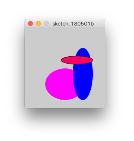
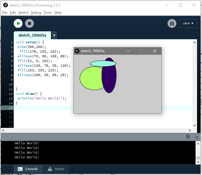
1: Ellipses
The exercise here is to play with ellipses. Our assignment was to copy a given image on the top left.
Its basically 3 ellipses with different shapes, colors and location.
Below you can find the code that was used to achieve this.
Basically we used the ellipse() function to create different shapes of ellipse.
In the parameter, you can give the x- and y-location of they location and then the width and height.
You have to use fill() to fill the ellipse. The hardest part is to find the right locations for the ellipses.
My result is on the bottom left, too me their almost the same its the idea that counts.
        void setup() {
            size(300,200);
            fill(178, 255, 102);
            ellipse(70, 80, 100, 80);
            fill(51, 0, 102);
            ellipse(120, 70, 50, 120);
            fill(153, 255, 225);
            ellipse(100, 30, 90, 20);
        }

        void draw() {
            println("Hello World!");
        }
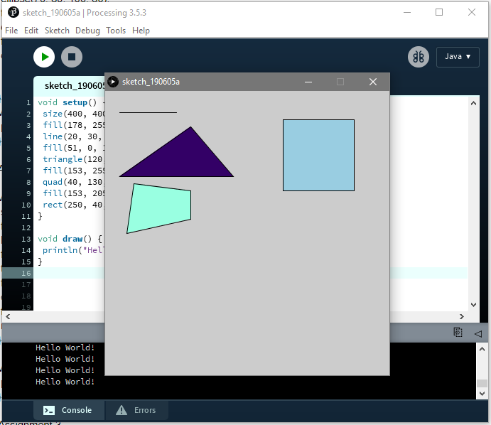
2: Different Shapes
The exercise here is to play with other shapes than ellipses. Our assignment was to draw 4 different shapes.
Below you can find the code that was used to achieve this.
Processing has built in shapes like line(), triangle(), quad(), rect() and that's why it's easy to program in processing.
I experimented with these functions to create different shapes. It's
basically give the functions the necessary arguments.
    void setup() {
        size(400, 400);
        fill(178, 255, 102);
        line(20, 30, 100, 30);
        fill(51, 0, 102);
        triangle(120, 50, 180, 120, 20, 120);
        fill(153, 255, 225);
        quad(40, 130, 120, 140, 120, 180, 30, 200);
        fill(153, 205, 225);
        rect(250, 40, 100, 100);
    }

    void draw() {
        println("Hello World!");
    }
3: Mouse interaction
The exercise here is to play with mouse interaction within Processing.
Here we can let a shape interact with the mouse.
Below you can find the code that was used to achieve this.
First we get the x and y from the mouse location and diameter and set it as color value.
Secondly we increase the diameter every time the draw() function is called and use the mouse x and y as the location for the ellipse.
We don't want to diameter to be bigger than the screen so we reset when it's over 100
    int diameter = 10;

    void setup() {
        size(255, 255);
        background (200, 200, 200);
        frameRate(15);
    }

    void draw() {
        fill(mouseX, mouseY, diameter);
        ellipse(mouseX, mouseY, diameter, diameter);
        diameter++;
        if (diameter > 100) {
            diameter = 10;
        }
    }
Part 2: Computer Vision
The assignment was to follow the a given tutorial. For this assignment we had to download a couple libraries for processing. Libraries are extentions that allows you as a developer to do extra things that is beyond the basic of the program itself. We had to download a library that allows us to use to use video and camera. For tracking our face we had to download OpenCV library. Other libraries were to track to brightness source in the room and to track to multiple colors. Each of these library has code examples so it was easy to use to follow.
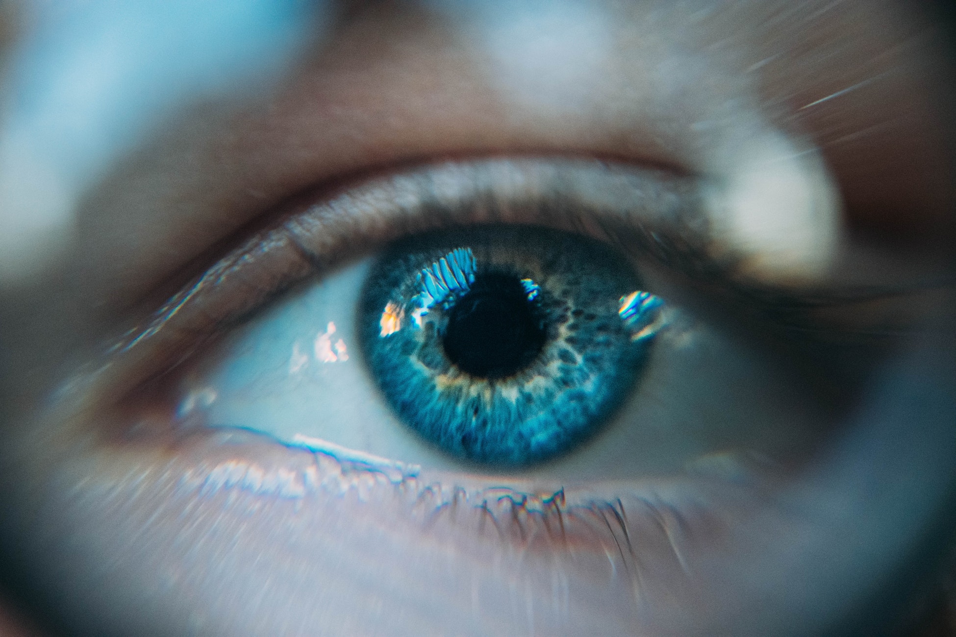
1: Facial Recognition
The exercise here is to experiment with facial recognition.
The library OpenCV en Video were used to able to get a circle around someone's face. Our assignment to change the rectangle around the face to an ellipse.
Below you can find the code that was used to achieve this.
Most of the code were from a example.
We looked for a the rect() function since in the previous assignment we learned that rect() is used to create a rectangle.
After that we change it to ellipse().
        import gab.opencv.*;
        import processing.video.*;
        import java.awt.*;

        Capture video;
        OpenCV opencv;

        void setup() {
            size(640, 480);
            video = new Capture(this, 640/2, 480/2);
            opencv = new OpenCV(this, 640/2, 480/2);
            opencv.loadCascade(OpenCV.CASCADE_FRONTALFACE);
            video.start();
        }

        void draw() {
            scale(2);
            opencv.loadImage(video);

            image(video, 0, 0 );

            noFill();
            stroke(0, 255, 0);
            strokeWeight(3);
            Rectangle[] faces = opencv.detect();
            println(faces.length);

            for (int i = 0; i < faces.length; i++) {
                println(faces[i].x + "," + faces[i].y);
                ellipseMode(CORNER);
                ellipse(faces[i].x,
                        faces[i].y,
                        faces[i].width,
                        faces[i].height);
            }
        }

        void captureEvent(Capture c) {
            c.read();
        }
2: Anonymous
The exercise here is to experiment with facial recognition.
The library OpenCV en Video were used to able to get a circle around someone's face. Our assignment to hide our eyes with a black rectangle making me anonymous.
Below you can find the code that was used to achieve this.
Most of the code were from a example.
We added a extra line for the black rectangle and you guess it using the rect() function and move it down to match the eyes.
            import gab.opencv.*;
            import processing.video.*;
            import java.awt.*;

            Capture video;
            OpenCV opencv;

            void setup() {
                size(640, 480);
                video = new Capture(this, 640/2, 480/2);
                opencv = new OpenCV(this, 640/2, 480/2);
                opencv.loadCascade(OpenCV.CASCADE_FRONTALFACE);

                video.start();
            }

            void draw() {
                scale(2);
                opencv.loadImage(video);

                image(video, 0, 0 );

                noFill();
                stroke(0, 255, 0);
                strokeWeight(3);
                Rectangle[] faces = opencv.detect();
                println(faces.length);

                for (int i = 0; i < faces.length; i++) {
                    println(faces[i].x + "," + faces[i].y);
                    ellipseMode(CORNER);
                    fill(0, 0, 0);
                    noStroke();
                    rect(faces[i].x,
                         faces[i].y + 30,
                         faces[i].width,
                         35);
                    stroke(0, 255, 0);
                    strokeWeight(3);
                    noFill();
                    ellipse(faces[i].x,
                            faces[i].y,
                            faces[i].width,
                            faces[i].height);
                }
            }

            void captureEvent(Capture c) {
                c.read();
            }
3: Other Libraries
The exercise here is to experiment with other libraries.
2 different libraries were given to us. Our assignment was to use one of these libraries to make something cool.
I experimented with the brightness one. The library uses the camera and circles the brightest source.
Below you can find the code that was used to achieve this.
Most of the code was download with the library.
What I changed was to color the whole background based on the brightest location. So the location x and y wil be used as red and green in rgb color value.
        import gab.opencv.*;
        import processing.video.*;

        OpenCV opencv;
        Capture video;

        void setup() {
            size(640, 480);
            video = new Capture(this, 640, 480);
            opencv = new OpenCV(this, 640, 480);

            video.start();

        }

        void draw() {
            opencv.loadImage(video);

            image(video, 0, 0 );

            PVector loc = opencv.min();

            stroke(255, 0, 0);
            strokeWeight(4);
            background(loc.x, loc.y, 50);
        }

        void captureEvent(Capture c) {
            c.read();
        }
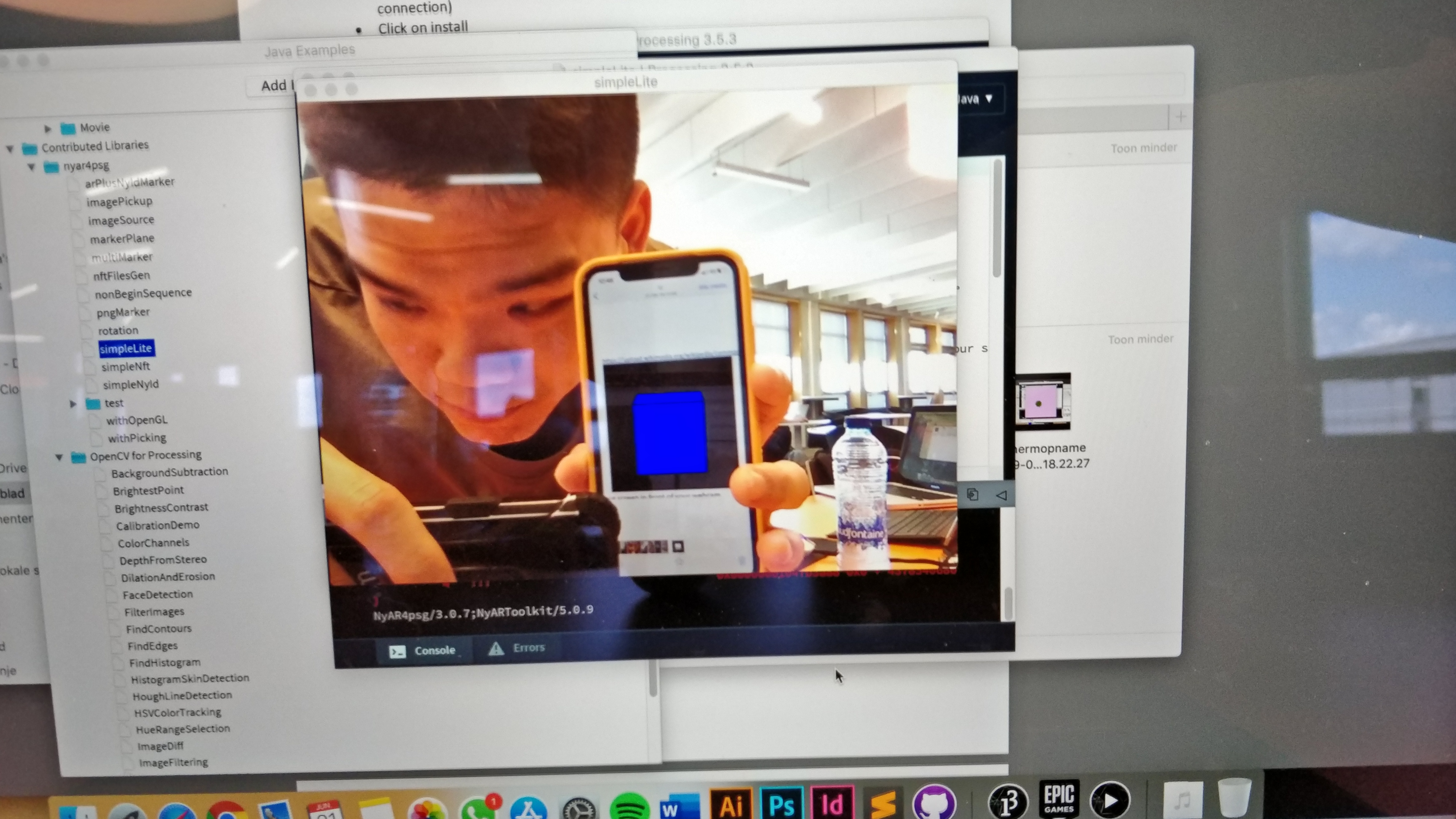
AR1: Markers
The exercise here is to experiment with augmented reality in Processing.
We had to download NyARToolkit library. This library allow us to recognize markers and augment these with other images.
Below you can find the code that was used to achieve this.
The code was the examples that were included in the library.
You can find these at File > Examples.
Basically this assignment to try different images out and see what the results were.
        import gab.opencv.*;
        import processing.video.*;

        OpenCV opencv;
        Capture video;

        void setup() {
            size(640, 480);
            video = new Capture(this, 640, 480);
            opencv = new OpenCV(this, 640, 480);

            video.start();

        }

        void draw() {
            opencv.loadImage(video);

            image(video, 0, 0 );

            PVector loc = opencv.min();

            stroke(255, 0, 0);
            strokeWeight(4);
            background(loc.x, loc.y, 50);
        }

        void captureEvent(Capture c) {
            c.read();
        }